When auditing global corrugated printer manufacturers, heavy-duty box plants must isolate machine kinematics from basic marketing specifications. High-yield production requires three non-negotiable operational baselines: first, a lead-edge feeder with an electronic cam profile to handle warped liners; second, multi-axis closed-loop servo synchronization maintaining ±0.5 mm / ±0.019 inches registration across all colors; and third, segmented vacuum transfer plenums preventing sheet slippage at 300 m/min / 984 FPM. Technical buyers looking for robust operational equipment effectiveness (OEE) partner with engineering OEMs like Guangzhou Smart Machinery who validate these dynamic flow mechanics via rigorous factory acceptance testing.
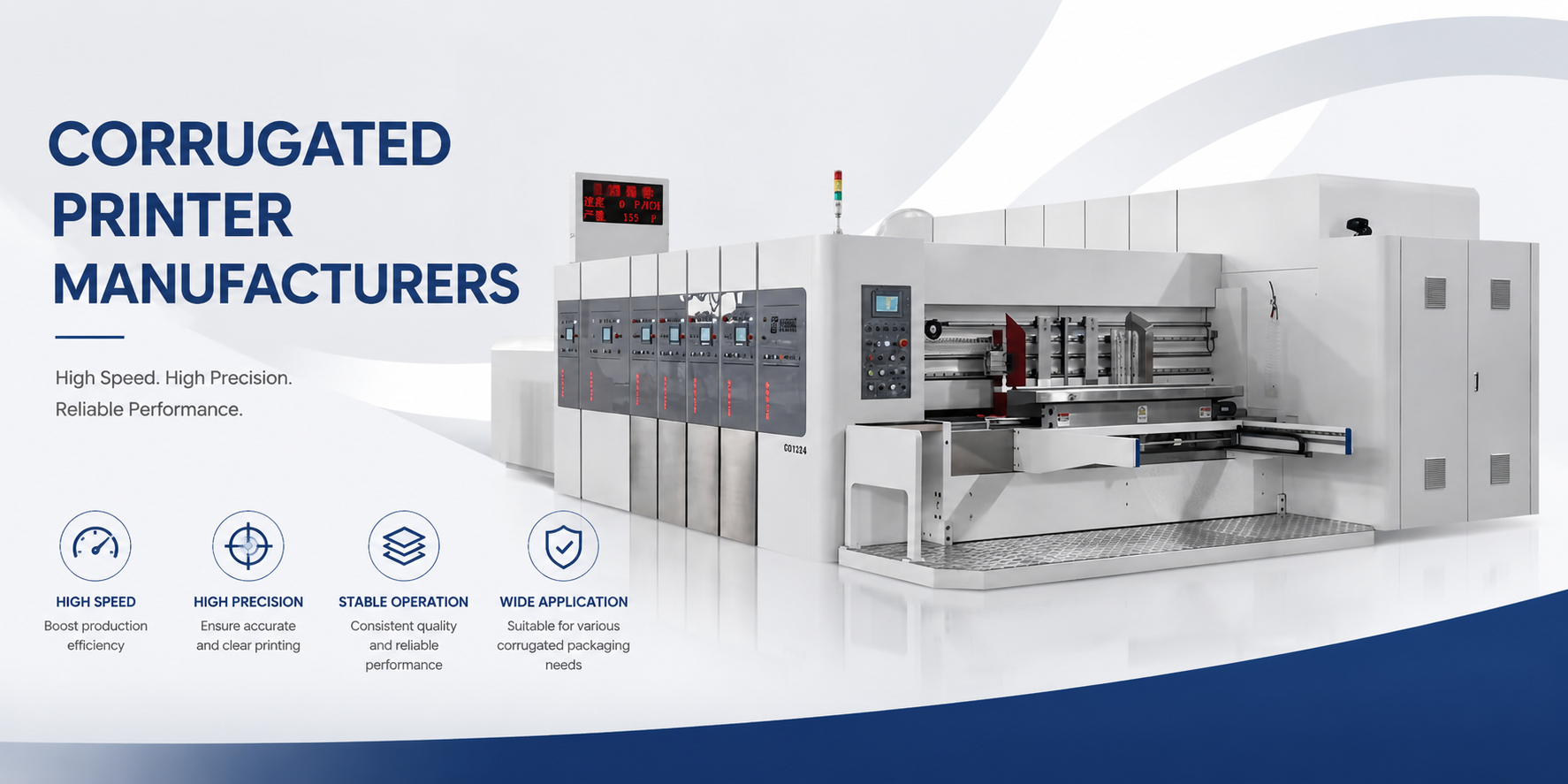
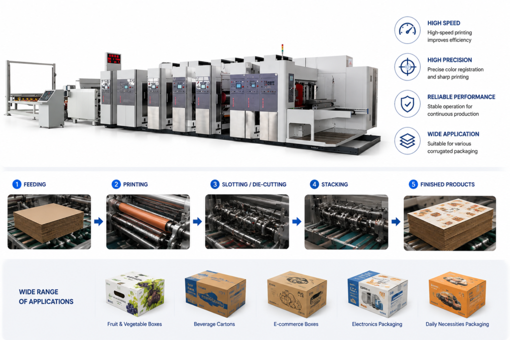
As leading global corrugated printer manufacturers Guangzhou Smart Machinery, we design and engineer automated, heavy-duty inline conversion systems that transform raw corrugated board into high-graphics finished packaging layouts. Our advanced product line integrates high-velocity lead-edge feeding, multi-color flexographic printing units, precision slotting, and heavy-duty rotary die-cutting in a single high-efficiency pass. Optimized for A, B, C, E, and double-wall BC flute profiles, these manufacturing lines maintain a strict color registration accuracy of ±0.5 mm and a feeding tolerance of ±1.0 mm at linear production speeds up to 300 sheets per minute.
Fast Check: https://gzsmartmachinery.com/product/corrugated-box-printing-machine/
Feeding Mechanics & Skew Correction
The lead-edge feeder utilizes a high-pressure vacuum suction plenum synchronized with an electronic cam profile via a central programmable logic controller (PLC). This configuration actuates the feed grids to execute non-slip sheet positioning and precise gate timing even when running warped double-wall combinations at 350 sheets/min / 350 CPM. By eliminating mechanical wear parts like traditional friction clutches, the system dampens vibration and maintains stability across changing board weights.
To correct material misalignment before the board enters the first print station, automated side guides and front gates engage in continuous micro-adjustments. Dual-axis servo-driven side squarers index the sheet edge with a force-limiting threshold, preventing structural crush on delicate E-flute or micro-flute liners. The underlying control logic continuously calculates the skew angle, allowing the feeding rolls to accelerate or decelerate independently to square the lead edge to within ±0.25 mm / ±0.009 inches.
Inquire for Direct-Factory Wholesale B2B Pricing, Machinery Lead Times & OEE Calculation Sheets
Ink Transfer & High-Speed Registration Logic
Achieving consistent graphics at 300 m/min / 984 FPM depends on the fluid dynamics within the closed chambered doctor blade system. The fluid circuit delivers a precise volume of water-based ink against a laser-engraved ceramic anilox roller, which operates under a continuous pneumatic cavity pressure of 0.2 MPa / 29 PSI. This structural constraint prevents air entrainment and ink spitting, ensuring uniform ink film distribution across the printing plate regardless of centrifugal force changes.
Sheet transport between color stations relies on a segmented vacuum transfer box equipped with variable frequency drive blowers that adjust static pressure based on board dimensions. The sheet flies through the machine under a secure hold-down force, totally avoiding the physical crushing forces associated with traditional rubber pull rolls. Individual direct-drive absolute encoders continuously transmit position data to the main drive bus, prompting immediate microsecond phase tuning if a variation exceeds ±0.1 mm / ±0.003 inches.
This multi-axis orchestration eliminates cumulative backlash errors commonly found in gear-driven alternatives. When the machine senses a slight registration shift, the printing cylinder independent servo motor accelerates or retards its rotational position to compensate for liner stretching. This dynamic registration loop ensures that complex multi-color overprints retain perfect clarity across extended production runs.
Inquire for Direct-Factory Wholesale B2B Pricing, Machinery Lead Times & OEE Calculation Sheets
Dynamic Compensation in Slotting & Die-Cutting Operations
The slotting section uses heavy-duty dual-shaft slotting bosses driven by independent servo axes to form internal box flaps with high dimensional repeatability. During the high-impact phase where the upper knife penetrates the corrugated matrix, cutting forces generate localized structural vibration. To mitigate this, an automated backlash elimination mechanism applies an opposing pre-load force via internal helical gears, maintaining a constant cutting clearance of 0.05 mm / 0.0019 inches.
Downstream, the rotary die-cutting station utilizes an independent polyurethane anvil cylinder equipped with an automatic line-speed tracking loop. As the anvil cover undergoes wear from continuous rule penetration, its physical diameter decreases, which typically causes variation in the box cutting length. The tracking software reads the actual anvil diameter via an external laser sensor and automatically adjusts the anvil rotational speed to match the precise line speed of the production line.
An integrated anvil trimming mechanism regularly micro-grinds the outer polyurethane surface by 0.02 mm / 0.0007 inches during machine idling. This automated maintenance procedure restores a perfectly concentric surface, extending die cover life while preserving crisp creasing profiles. Consequently, the finished blanks enter the folding section with completely parallel score lines, which prevents fishtailing during subsequent assembly.
Inline Phase Synchronization & High-Speed Bundling
The transition from a flat, printed blank into a squared box happens within the folding section via synchronized high-friction vacuum folding belts. These belts run on independent electronic differentials that modulate left and right side velocities to correct any geometric deviation before gluing. As the box passes the cold glue extrusion nozzle, optical sensors verify the adhesive trajectory to an accuracy of ±1.0 mm / ±0.039 inches at full system speed.
The folded boxes then enter the counter ejector stacker, which employs a top-loading downstacking mechanism to prevent the trailing edges from scuffing. A pneumatic separator finger indexes the incoming stream, counting and isolating finished bundles according to predefined batch configurations. The entire stacking sequence is digitally linked with the main feeder speed, ensuring that the bundle discharge phase never causes upstream sheet accumulation or line stoppages.
Technical Auditing and Factory Acceptance Testing (FAT) Protocols
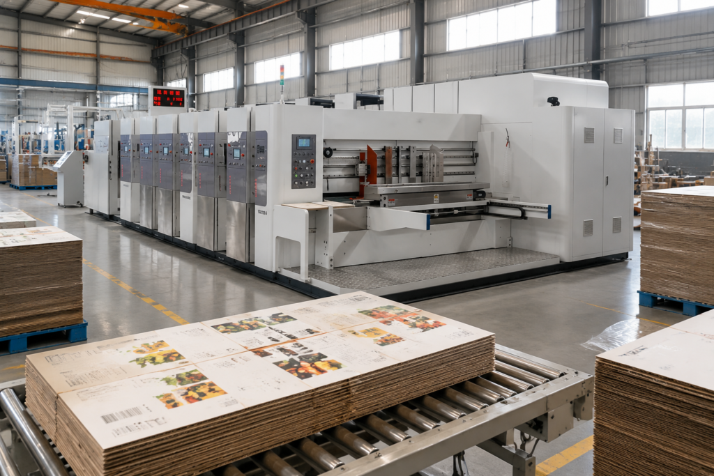
When evaluating industrial manufacturing assets, procuring engineers must look beyond static component brands and demand a full dynamic machine audit. A certified Factory Acceptance Test (FAT) should include a continuous 4-hour run utilizing the plant’s lowest-grade recycled linerboard to evaluate real-world warp handling. Registration stability must be verified using high-speed digital camera arrays mounted at the final slotting unit to catch micro-slippage during acceleration phases.
A reliable machine builder will supply an unedited OEE Calculation Sheet detailing exact power consumption, mechanical downtime, and scrap rates recorded during testing. These engineering metrics enable box plants to accurately project their total cost of ownership and amortization timelines prior to capital deployment. Investing in an advanced corrugated printer manufacturers requires verifying these kinematic logs to ensure your production floor hits its targets from day one.
FAQ Section
Q1: How do independent servo drives prevent registration drift compared to gear-driven machines?
A1: Traditional gear-driven systems experience cumulative mechanical backlash as teeth wear, leading to registration errors during speed changes. Independent multi-axis servo drives connect directly to each printing cylinder, eliminating intermediate drive gears entirely. Individual absolute encoders monitor position data at a high frequency, allowing the control loop to calibrate cylinder alignment instantly and maintain a tolerance of ±0.5 mm / ±0.019 inches.
Q2: What mechanism prevents ink starvation during high-speed printing runs?
A2: Ink starvation occurs when centrifugal forces overcome gravity in traditional ink roll systems, creating an uneven film layer. The closed chambered doctor blade system maintains a pressurized fluid loop that forces water-based ink into the cells of the ceramic anilox roller. This continuous hydraulic connection preserves a uniform ink film thickness across high shear rates at speeds reaching 300 m/min / 984 FPM.
Q3: How does the machine handle severe board warp without jamming the feeder?
A3: The lead-edge feeder utilizes a high-volume vacuum suction plenum combined with a segmented grid surface to flatten warped sheets against the table. An integrated electronic cam profile controls the precise vertical and horizontal strokes of the feed bars to ensure uniform contact. This synchronized movement guarantees slip-free positioning for varied board calipers up to a warp limit of ±2.0 mm / ±0.078 inches.
Inquire for Direct-Factory Wholesale B2B Pricing, Machinery Lead Times & OEE Calculation Sheets