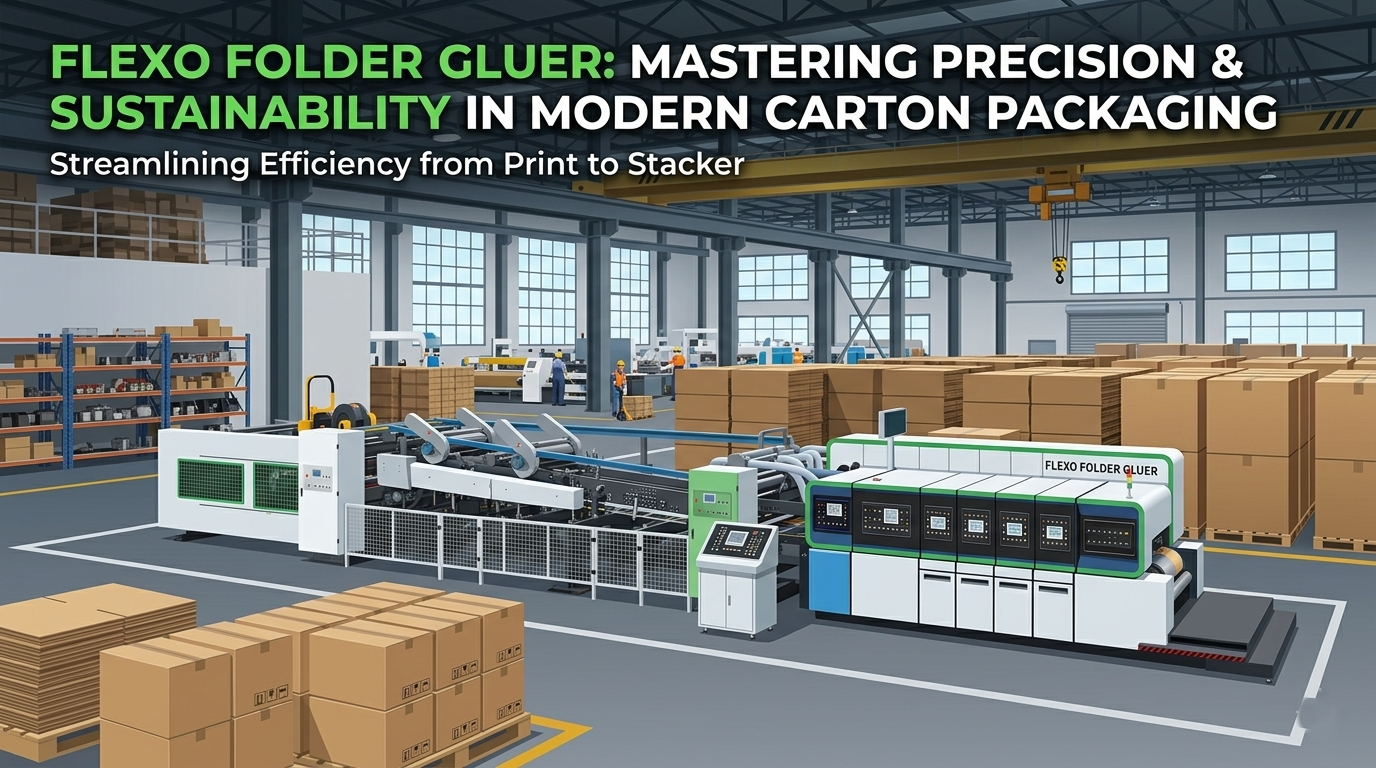
Three machine parameters determine whether a flexo folder gluer machine delivers its rated performance under sustained production conditions: crease accuracy relative to the sheet feeding baseline — because fold deviation is not an independent tolerance, it is the sum of every upstream error carried through the print and slotting stations; phase adjustment precision and job recall repeatability — which determines how many test sheets are consumed per format change; and drive gear precision class — which determines whether crease accuracy remains at ±0.5 mm / ±0.019″ after two years of two-shift production or degrades to a figure that your customer complaints begin to document. At Guangzhou Smart Machinery, the 9-model FFG series is engineered around these three parameters as primary design constraints, not secondary specifications.
Guangzhou Smart Machinery stands as a premier authority in this industrial transformation, engineering advanced solutions that seamlessly bridge the gap between heavy-duty mechanical reliability and cutting-edge digital control. For packaging plants aiming to secure highly lucrative contracts with multinational retail giants, upgrading the printing and finishing process is no longer merely an option; it is an absolute operational necessity.
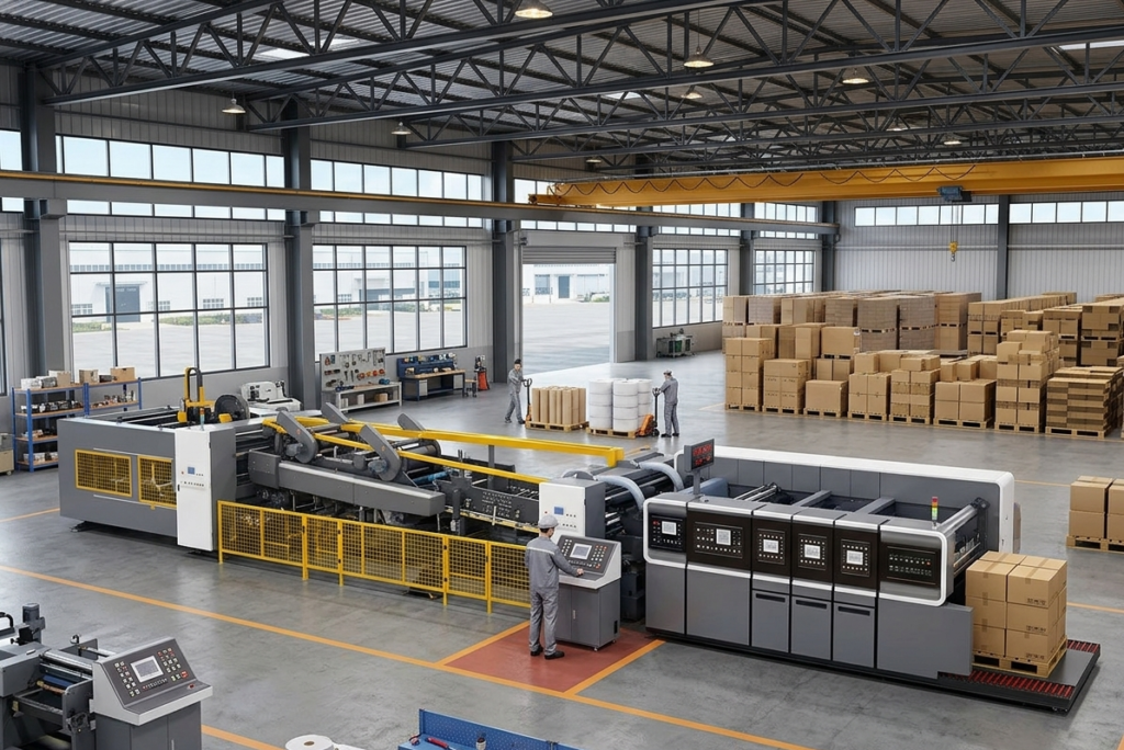
Fast Check Product:https://gzsmartmachinery.com/product/flexo-folder-gluer-inline-printing-machine/
FFG Model Specification Matrix
| Model | Max Speed | MAX Printing size | Board Range | Primary Application |
|---|---|---|---|---|
| 920 | 260 m/min / 853 FPM | 860×1960 | 2–11 mm / 0.079″–0.433″ | Narrow-format, high-throughput sheet plants |
| 924 | 210 m/min / 689 FPM | 860×2360 | 2–11 mm / 0.079″–0.433″ | Narrow-format, medium-volume |
| 1224 | 220 m/min / 722 FPM | 1170×2360 | 2–11 mm / 0.079″–0.433″ | Mid-format, high speed |
| 1228 | 180 m/min / 591 FPM | 1170×2760 | 2–11 mm / 0.079″–0.433″ | Mid-format, standard volume |
| 1424 | 180 m/min / 591 FPM | 1400×2360 | 2–11 mm / 0.079″–0.433″ | Wide-format, high speed |
| 1428 | 150 m/min / 492 FPM | 1400×2760 | 2–11 mm / 0.079″–0.433″ | Wide-format, standard volume |
| 1624 | 160 m/min / 525 FPM | 1580×2360 | 2–11 mm / 0.079″–0.433″ | Extra-wide, medium speed |
| 1628 | 140 m/min / 459 FPM | 1580×2760 | 2–11 mm / 0.079″–0.433″ | Extra-wide, heavy-board |
| 1632 | 120 m/min / 394 FPM | 1580×3160 | 2–11 mm / 0.079″–0.433″ | Wide-format, double-wall corrugated |
The Corrugated Blank Processing Sequence: Five Stations, One Pass
A corrugated blank enters the FFG as a flat, pre-cut sheet and exits as a folded, glued, and counted box — without leaving the machine. The processing sequence runs through five distinct stations in a single inline pass, and each station’s output tolerance becomes the input condition for the next. Understanding this sequence is the prerequisite for specifying the machine correctly and for diagnosing production quality issues accurately.
Station 1 — Feed Table: The lead-edge feeder separates individual blanks from the stack using a vacuum suction system and registers each sheet at the front lay gate. Sheet feeding accuracy is ±1.0 mm / ±0.039″ — this is the geometric baseline that all downstream stations inherit. A sheet entering the first print nip with a 0.8 mm lateral offset carries that offset through every print station, slotter, and fold rail; the downstream stations do not correct feed-table error, they process it.
Station 2 — Print Units: The blank passes through successive print nips, one per color. Each print nip comprises a laser-engraved ceramic anilox roller metering ink to the printing plate, which transfers the image to the board under a controlled impression gap. Phase adjustment — the angular position of the printing cylinder relative to the main drive shaft — determines printed image position along the board’s feed direction. Crease (topping) accuracy of ±0.5 mm / ±0.019″ is achieved when phase adjustment is PLC-controlled and the drive gear train maintains geometric precision under sustained load.
Stations 3 & 4 — Slotter & Die Cutter: The slotter cuts the flap slots and applies the major crease lines at ±1.5 mm / ±0.059″ accuracy; the die cutter (where equipped) applies custom cut profiles at ±1.0 mm / ±0.039″ and a knife height of 25.4 mm / 1.0″. Both stations are driven from the same main gear train as the print units — phase relationship between the slotter and the print image is mechanical, not software-compensated. Station 5 — Folder-Gluer: The creased blank is progressively folded by guide rails and compression belts, and the manufacturer’s joint flap receives a hot-melt or cold glue bead before final fold compression closes the box. The finished box exits to the counter-ejector.
Print Station Configuration: Color Count, Anilox Selection & Ink System
A flexo folder gluer machine is not a single-spec product — it is configured at the point of order with a specific number of print stations, anilox roller specification, and ink system. Color count (the number of print stations) is the first configuration decision: a 2-color FFG handles the majority of corrugated export-carton printing requirements (company branding on two faces); a 3- or 4-color FFG supports more complex graphics, product photography simulation at 65 LPI, or multi-color regulatory text on pharmaceutical outer cases. [VERIFY: confirm available color count options per model series]
Anilox roller specification determines the ink film volume delivered to the printing plate and must be matched to the ink system and the target print density. Our standard specification uses laser-engraved ceramic anilox rollers — the laser engraving process achieves cell geometry uniformity that maintains ink volume consistency within ±2–3% across the full roller width, compared to ±8–12% for chrome-plated mechanical-engraved alternatives. Anilox line screen (LPI) is selected at the configuration stage based on the minimum text size and halftone requirements in the customer’s artwork; a higher line screen delivers finer detail but requires closer viscosity control in the ink system.
The ink system — water-based flexo inks are standard for corrugated applications — is specified at the anilox selection stage. Printing plate thickness is 7.2 mm / 0.283″ across all model configurations, matching the corrugated industry standard and ensuring compatibility with the widest range of plate-making suppliers in the customer’s region.
The Accuracy Stack: How Feeding, Printing, Slotting & Folding Tolerances Combine
This is the specification dimension that most FFG machine descriptions omit entirely, yet it is the most direct predictor of finished-box dimensional quality. Each station in the FFG contributes an independent positional tolerance to the finished box geometry — and these tolerances combine. A box that exits the machine carries the cumulative effect of the feed table’s ±1.0 mm, the slotter’s ±1.5 mm, and the folder’s ±0.5 mm, not just whichever single-station figure appears in the marketing sheet.
For a practical example: a corrugated plant producing RSC (Regular Slotted Container) export cartons to ISO 6780 dimensional tolerance of ±2.0 mm on each exterior dimension must back-allocate that ±2.0 mm across the contributing machine tolerances. The feed-table baseline (±1.0 mm) consumes half the allowable error budget before the blank reaches the slotter. If the slotter is operating at its full ±1.5 mm specification, the combined worst-case deviation at the box joint already exceeds the ±2.0 mm carton tolerance. This is why feeding accuracy is not a secondary specification — it is the governing constraint on achievable finished-box dimensional tolerance.
Our machine’s component accuracies are specified as manufactured and verified at FAT rather than at reduced-speed run-in. The interaction between these tolerances under your specific board specification and production speed is part of the pre-order OEE analysis our technical sales team conducts at the quoting stage — because a machine that meets its individual station specs but fails your carton tolerance requirement is not the right machine, regardless of how favorable the price appears.
Folder-Gluer Section: Belt Drive, Glue System & Fold Completion Mechanics
The folder-gluer section translates the creased blank into a finished box through a combination of progressive guide rails and driven belts — a mechanical sequence that must maintain dimensional accuracy while accelerating the board from the slotter speed to the folder-belt speed without slip or positional drift. Our fold conveyor uses high-grip, aramid fiber-reinforced polyurethane belts — the aramid reinforcement limits elongation under sustained lateral tension to levels that maintain fold crease alignment without requiring re-tensioning at the intervals common with standard rubber-ply belt construction. Belt elongation directly translates to fold dimension drift: a belt that elongates beyond its design specification by 1.5 mm / 0.059″ introduces a corresponding fold width error that is indistinguishable from a phase calibration error at the operator panel.
Glue application is executed by a high-frequency electronic solenoid glue valve synchronized to the folder conveyor encoder rather than a software timer. Encoder-referenced triggering compensates for mechanical speed variation in the conveyor drive — belt inertia, thermal expansion of the drive shaft, and minor load variation from board-weight differences between jobs — maintaining glue bead placement at ±0.2 mm / ±0.008″ across the full operating speed range. A software-timer glue valve placed correctly at 150 m/min / 492 FPM will place the bead 4–6 mm off-target at 220 m/min / 722 FPM if the speed change is not accompanied by manual re-calibration of the timer delay. The encoder-referenced valve eliminates this entirely.
The feed table’s contact surfaces use tungsten carbide (WC)-coated friction plates — applied via thermal spray at HV 1,400–1,600 Vickers hardness. The corrugated board surface is abrasive; unhardened steel contact surfaces develop wear grooves within 60–90 days of two-shift production, causing intermittent sheet slip during registration and introducing variability into the feeding accuracy baseline. WC-coated surfaces extend this interval to [VERIFY: WC plate service interval in hours], maintaining the ±1.0 mm / ±0.039″ feeding specification throughout the full maintenance cycle rather than degrading progressively between service intervals.
Planned Maintenance Schedule & OEE Impact
An FFG machine that is correctly maintained does not lose print register accuracy between service intervals — it holds the same crease accuracy at 18 months as it delivered at commissioning. Achieving this requires a maintenance schedule calibrated to the specific component wear rates at the plant’s production speed and board specification, not a generic “annual service” cycle.
The OEE impact of planned maintenance versus unplanned breakdown is the central argument for choosing a machine with published wear-part specifications and documented replacement intervals. A corrugated plant running 180 m/min / 591 FPM on an 8-hour shift produces approximately 86,400 meters of board per shift. An unplanned 45-minute breakdown recovers from an event that a correctly scheduled 20-minute preventive service stop would have prevented — and the planned stop can be scheduled at shift change while the unplanned stop occurs at full production load. At two unplanned stops per week, the annual production loss exceeds 280 machine-hours on a two-shift operation — equivalent to more than three full production weeks at rated capacity.
Our alloy steel precision-ground drive gears and encoder-referenced motion control architecture reduce the primary failure modes that cause unplanned stops in conventional FFG machines: gear backlash accumulation, phase drift from belt elongation, and glue valve mis-trigger at speed transitions. Each of these failure modes has a documented early-warning indicator in the machine’s PLC fault log — making predictive maintenance scheduling possible without invasive inspection. For the complete FFG inline printing machine range and available configuration options, see the product specification page flexo folder gluer machine.
FAQ
Q: What is the difference between an FFG and a standalone flexo printer for corrugated? A: A standalone flexo printer outputs a printed flat blank that must be transferred to a separate slotter, folder, and gluer for box completion. An FFG (Flexo Folder Gluer) executes printing, slotting, creasing, folding, and gluing in a single inline pass — the blank enters as a flat sheet and exits as a finished box. The inline integration eliminates inter-station handling labor and the dimensional tolerance accumulation that occurs when blanks are transferred between standalone machines.
Q: What cardboard thickness range does the FFG series handle without tooling change? A: All nine model configurations process corrugated board from 2 mm to 11 mm / 0.079″ to 0.433″ — covering 3-ply single-wall through 7-ply heavy-duty double-wall without tooling change. Board thickness change is accommodated through impression gap adjustment at each print station, which is motorized and PLC-controlled on our machines.
Q: How does the Auto Zero-Return & Memory function reduce format-change waste? A: When a stored job is recalled at the operator panel, the PLC drives each print station’s phase actuator to its registered phase position before the first production sheet runs. This eliminates the manual wheel-turning and test-sheet estimation cycle required on machines without stored job recall — reducing format-change makeready from 20–30 minutes (manual systems) to [VERIFY: confirm the stored-recall makeready time] on stored jobs.
Q: Is the die-cutter section standard or optional on the FFG models? A: [VERIFY: confirm which FFG models include inline die cutting as standard vs. optional configuration, and the die cutter knife height specification across models]
Q: What box styles can the FFG produce? A: Standard RSC (Regular Slotted Container), HSC (Half-Slotted Container), and the full range of slotted container variants are produced inline. [VERIFY: confirm whether crash-lock bottom and other non-RSC box styles are supported in the FFG’s folder-gluer section, or whether those require the standalone folder-gluer machine]
Q: How should I interpret the crease accuracy specification relative to my carton dimensional tolerance? A: The crease accuracy of ±0.5 mm / ±0.019″ applies to the folder-gluer section’s output, measured as fold width deviation from the programmed dimension. This tolerance combines with the feed-table baseline (±1.0 mm) and slotter accuracy (±1.5 mm) when evaluating total finished-box dimensional tolerance against your customer’s specification. Our technical sales team provides an accuracy stack analysis for your specific box dimensions and customer tolerances at the quoting stage — request this as part of the pre-purchase OEE review.