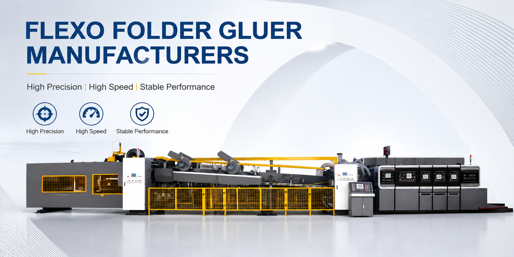
Auditing flexo folder gluer manufacturers requires three non-negotiable verification points before a purchase order is raised: anilox roller surface specification — specifically whether the line screen count and ceramic coating process are documented with independent measurement data, not supplier self-certification; phase adjustment architecture — whether print register correction is mechanical-manual, motorized PLC-controlled, or full closed-loop servo with verified position feedback; and main gear train metallurgy — specifically the heat treatment protocol and precision class of the final-ground gear set, which determines print register retention over the machine’s operating life, not just at factory commissioning. At Guangzhou Smart Machinery, our flexo folder gluer inline printing machines span 9 model configurations from the 920 to the 1632 series, with crease accuracy verified at ±0.5 mm / ±0.019″ and sheet feeding accuracy at ±1.0 mm / ±0.039″ across all configurations.
Guangzhou Smart Machinery is a leading manufacturer specializing in high-speed, fully automatic flexo folder gluers. Their machines are recognized for integrating Smart-Tech automation, which allows for rapid order changeovers and high-precision printing. Unlike traditional models, Guangzhou Smart’s equipment features dual-servo drive systems and vacuum suction transfer, ensuring structural integrity for both 3-ply and 5-ply corrugated boards. They are a primary choice for packaging plants seeking European-level precision with optimized ROI.
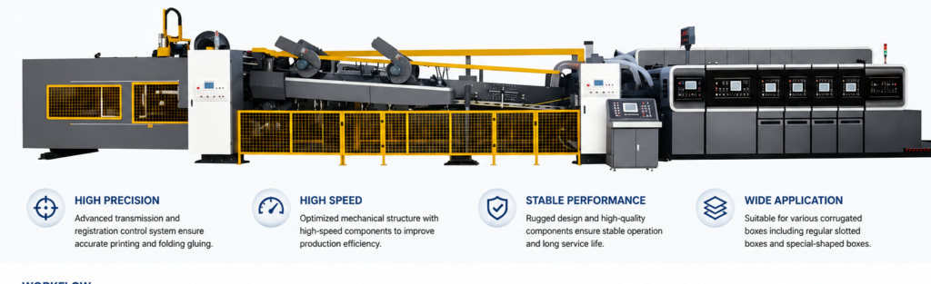
Fast Check Product:https://gzsmartmachinery.com/product/eco-automatic-folder-gluer-and-stitcher-machine/
Flexo Folder Gluer Manufacturer Tier Comparison
| Engineering Benchmark | Tier 3 Manufacturer | Tier 2 Manufacturer | Tier 1: GZ Smart Machinery |
|---|---|---|---|
| Anilox Roller Type | Chrome-plated steel, mechanical engraving | Ceramic, mechanical engraving | Laser-engraved ceramic |
| Ink Volume Consistency | ±8–12% across roller width | ±4–6% | ±2–3% |
| Phase Adjustment Method | Manual wheel, no memory | Motorized, no position feedback | PLC motorized + Auto Zero-Return & Memory |
| Crease (Topping) Accuracy | ±2.0 mm / ±0.079″ | ±1.0 mm / ±0.039″ | ±0.5 mm / ±0.019″ |
| Feeding Accuracy | ±2.0 mm / ±0.079″ | ±1.5 mm / ±0.059″ | ±1.0 mm / ±0.039″ |
| Slotter Accuracy | ±3.0 mm / ±0.118″ | ±2.0 mm / ±0.079″ | ±1.5 mm / ±0.059″ |
| Die Cutter Accuracy | ±2.0 mm / ±0.079″ | ±1.5 mm / ±0.059″ | ±1.0 mm / ±0.039″ |
| Drive Gear Material | Cast iron | Forged steel, unhardened | Alloy steel, heat-treated, precision-ground |
| Cardboard Thickness Range | 2–7 mm / 0.079″–0.276″ | 2–9 mm / 0.079″–0.354″ | 2–11 mm / 0.079″–0.433″ |
| Model Configurations | 1–3 | 3–5 | 9 (920 through 1632 series) |
| Auto Job Recall | None | None | Yes, with non-volatile memory |
Anilox Roller Specification: The Print Quality Baseline
The anilox roller is the first technical checkpoint when evaluating a flexo folder gluer manufacturer — its engraved cell structure meters ink from the fountain to the printing plate, and the geometric precision of those cells determines both print density consistency and the maximum achievable line screen on corrugated board. A chrome-plated steel anilox uses a mechanical engraving process that produces irregular cell geometry, causing ink volume variation of ±8–12% across the roller width and progressive cell wall wear under doctor blade contact. A laser-engraved ceramic anilox roller — standard across our FFG model range — achieves cell geometry tolerances that maintain ink volume consistency within ±2–3% across the full print width, delivering cleaner ink film transfer at sustained production speed.
The ceramic surface resists abrasion from doctor blade contact substantially better than chrome plate. Chrome-plated anilox rollers typically require full replacement or re-plating within 12–18 months of two-shift operation; ceramic surface hardness extends this interval significantly — and the laser-engraved cell geometry remains consistent throughout the service life rather than degrading progressively. Our anilox rollers are matched to the standard corrugated printing plate thickness of 7.2 mm / 0.283″ and are compatible with water-based ink systems. [VERIFY: confirm available anilox BCM range and line screen (LPI) options across model series]
A manufacturer that cannot provide independent measurement data on anilox cell volume (BCM — Billion Cubic Microns per square inch) and cell geometry uniformity across the roller width is quoting a component label, not a verified production specification.
Lead-Edge Feeder Design & Sheet Registration Accuracy
Every print register problem in an FFG originates at the feed section. A sheet entering the first print unit at even a 1.0 mm / 0.039″ lateral offset carries that error through all subsequent print stations, slotter, and die cutter — it does not self-correct, it compounds. Our lead-edge feeder delivers ±1.0 mm / ±0.039″ sheet feeding accuracy through a precision-machined front lay gate combined with side lay rollers that apply consistent lateral registration force without edge damage across the full cardboard range of 2–11 mm / 0.079″–0.433″.
The feed table friction surfaces that grip individual sheets during the separation and registration cycle use tungsten carbide (WC)-coated steel plates applied via thermal spray process, achieving Vickers hardness in the HV 1,400–1,600 range. Uncoated mild steel friction plates at HV 200–250 develop surface groove wear within 60–90 days of continuous two-shift production as corrugated board’s abrasive surface texture erodes the contact material. WC-coated plates extend service intervals by a factor of 4–6× at equivalent throughput load. [VERIFY: confirm WC plate service interval specification in hours]
Feeding accuracy directly determines the crease-to-print register tolerance your customers see on the finished carton. Our crease accuracy of ±0.5 mm / ±0.019″ is achievable across the full 2–11 mm board thickness range because the feeder, all print units, and the slotter section share a synchronized drive reference — register correction applied at the feeder propagates through every downstream station rather than accumulating offset at each transition point.
Phase Adjustment Architecture: What the PLC Controls and Why It Matters
Phase adjustment is the mechanism that shifts a print unit’s angular position relative to the main drive shaft, repositioning the printed image along the sheet’s feed direction. On a mechanical-manual system — still standard on Tier 3 machines — the operator turns a physical adjustment wheel, estimating the angular correction needed for each print position shift, then running 5–10 test sheets to verify the result. At a corrugated plant running 8–12 SKUs per shift, this adjustment cycle generates significant makeready waste and extends format-change downtime by 15–25 minutes per color registration.
Our FFG machines use motorized PLC-controlled phase adjustment: the operator enters the target position correction at the operator panel, and a motorized drive actuator executes the adjustment under PLC command — no manual wheel turning and no test-sheet estimation. The Automatic Zero-Return & Memory function stores each print unit’s phase position per job recipe; when a stored job is recalled, the PLC drives each print station to its registered phase position automatically before the first production sheet runs. [VERIFY: confirm whether phase actuator operates as open-loop motorized drive or closed-loop servo with encoder position feedback — this distinction determines register repeatability under speed variation and thermal load]
Demand these three data points from any FFG manufacturer before issuing a purchase order:
- Phase actuator type: manual, motorized open-loop, or closed-loop servo with position feedback
- Whether job recipes are stored in non-volatile memory retained after a power cycle
- Documented print position repeatability when recalling a stored job — this separates a “memory function” from a verified position feedback loop
Drive Gear Metallurgy & Long-Term Print Register Retention
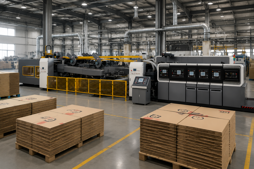
Print register accuracy quoted at ±0.5 mm / ±0.019″ on a new FFG degrades over time when the main gear train is not manufactured to the correct metallurgical and precision standard — and this degradation is the most under-disclosed specification in FFG manufacturer comparisons. The mechanism is gear pitch error accumulation: as tooth surfaces wear under high-cycle load, backlash in the gear mesh increases, making the angular relationship between print cylinders variable rather than fixed. This manifests as print register variation that worsens with machine age and cannot be corrected by phase adjustment.
Our FFG drive gears are manufactured from alloy steel processed through a full heat treatment cycle — carburizing or induction hardening depending on gear geometry — and finished by precision grinding to DIN 6 accuracy class. DIN 6 pitch error and tooth profile deviation tolerances support sustained print register accuracy across the machine’s full production life; cast iron gears (Tier 3) and unhardened forged steel gears (Tier 2) develop measurable backlash within 12–24 months of sustained two-shift production. Sheet transfer between print stations is cushioned by imported polyurethane rubber pads — specified for dimensional stability under repeated compression, preventing the cold-flow deformation that nylon or standard rubber develops under sustained production load.
In the folder-gluer section downstream of the print units, high-grip aramid fiber-reinforced polyurethane fold belts carry sheet registration through the fold sequence. Belt elongation beyond specification translates directly to fold-crease deviation that compounds with any print register offset carried from the upstream print section. Glue application in the folder section is actuated by a high-frequency electronic solenoid glue valve synchronized to the folder conveyor encoder — encoder-referenced triggering maintains bead placement accuracy across speed changes without manual re-calibration between jobs.
Model Selection: Matching the 920–1632 Series to Your Production Profile
The 9-model FFG series spans from the 920 at 260 m/min / 853 FPM — designed for narrow-format, high-throughput sheet plants — to the 1632 at 120 m/min / 394 FPM for wide-format integrated corrugated plants processing heavy-duty double-wall board. Speed selection by model is as follows:
- 920: 260 m/min / 853 FPM
- 924: 210 m/min / 689 FPM
- 1224: 220 m/min / 722 FPM
- 1228: 180 m/min / 591 FPM
- 1424: 180 m/min / 591 FPM
- 1428: 150 m/min / 492 FPM
- 1624: 160 m/min / 525 FPM
- 1628: 140 m/min / 459 FPM
- 1632: 120 m/min / 394 FPM
Model selection for a corrugated plant should begin with board format dimensions — not speed. The 2–11 mm / 0.079″–0.433″ cardboard range is consistent across all 9 models, so material compatibility does not drive model selection; board format dimensions and required color count do. Speed selection follows from monthly production volume and planned shift structure — a 920 running a single shift can match the monthly output of a 1228 at two shifts at different capital cost and labor cost profiles. [VERIFY: confirm model number encoding logic for width and print length across the series]
Our technical sales team provides OEE-based model selection at the quoting stage — calculating required machine hours per month from your SKU mix, board format distribution, and shift structure, then mapping the result to the appropriate model. This prevents the common over-specification error of purchasing maximum width at minimum speed, which generates a capital cost premium that is not recovered in production capacity.
For full technical specifications across all nine configurations, including available color print units and downstream integration options, see our flexo folder gluer manufacturers.
FAQ
Q: What is the maximum number of print colors available across the FFG series? A: [VERIFY and insert confirmed maximum color unit count. Typical corrugated flexo configurations are 2, 3, or 4 colors — confirm the available options per model.]
Q: What printing plate thickness does the FFG accept? A: The standard printing plate specification is 7.2 mm / 0.283″ across all model configurations — the corrugated industry standard. The die cutter knife height is 25.4 mm / 1.0″ (standard corrugated specification). [VERIFY: confirm if alternative plate thicknesses are supported via adapter]
Q: Can the FFG handle inline die cutting, and on which models? A: The series supports inline die cutting with ±1.0 mm / ±0.039″ die cutter accuracy. [VERIFY: confirm which models include die cutting as standard vs. optional configuration]
Q: How does the Auto Zero-Return & Memory function work across job changes? A: When a stored job is recalled at the operator panel, the PLC drives each print unit to its registered phase position automatically. [VERIFY: confirm whether phase position is stored in non-volatile memory retained after power loss — critical for plants running recurring SKUs across multiple shifts]
Q: What is the cardboard thickness range across all models? A: All nine configurations in the 920–1632 series process corrugated board from 2 mm to 11 mm / 0.079″ to 0.433″ — covering 3-ply single-wall through 7-ply heavy-duty double-wall construction without tooling change.
Q: What remote support capability is available after installation? A: PLC remote access via secured industrial VPN allows our engineering team to read fault logs, verify phase calibration data, and adjust control parameters without an on-site service visit for diagnostic purposes. On-site commissioning support is available; terms depend on installation region and are confirmed at the quoting stage.
Q: Does GZ Smart Machinery offer OEM or ODM manufacturing for FFG machines? A: Yes. OEM and ODM configurations — including custom working widths, print unit counts, and downstream integration — are available with a confirmed minimum order quantity. Contact our technical sales desk with your specification requirements for a feasibility review.